
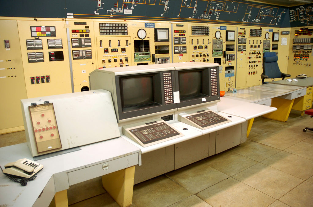
Control room – machinery on QP

- control flow rates from each producing well on CDP1 and DP2, and the total gas flow to Scotland
- control flow rates through each processing train on TP1 and TCP2
- control pressure in the pipelines to Scotland
- monitor temperature, pressure, flow rates and other process parameters in all equipment from every platform
- monitor the process in order to make adjustments in response to indications of abnormal conditions and to alarms
- maintain an overview of all valves and pumps, so that the correct interventions could be made in the process.
A mimic panel on the control room wall displayed all process equipment and alarm lights, as well as whether valves and pumps were closed or operational. Beneath this panel were metering instruments and printers covering all control points for temperature, pressure, flow rates and so forth. Control room staff could also communicate with personnel on the other platforms to give orders about work needing to be done. In order to be able to handle all this information in a secure way, control room operators were supported by computers which could predict what would happen if certain settings on the process equipment were changed.


The most important adjustments made from the control room were:
- adjusting the dryness of the gas by altering the temperature of the glycol regenerator and the flow of this chemical through the contactor’s gas exported to Scotland could not contain more than 67.5 parts per million of water, or 0.00675 per cent
- adjusting the flow rate of gas entering the pipelines to Scotland by changing the choke settings for each well
- altering the flow rate to ensure that the gas pressure on entering the pipelines, plus pressure loss en route and at the St Fergus terminal, met the British Gas Corporation’s delivery specification of 44 bar
- ensuring that the flow rate nevertheless exceeded four metres per second to prevent condensate mixed with the gas from separating out and accumulating at the bottom of the pipeline.
A separate control room on TCP2 was provided for the compressors when these were installed on the platform in 1981.
 Kontrollrom på QP, drift,