
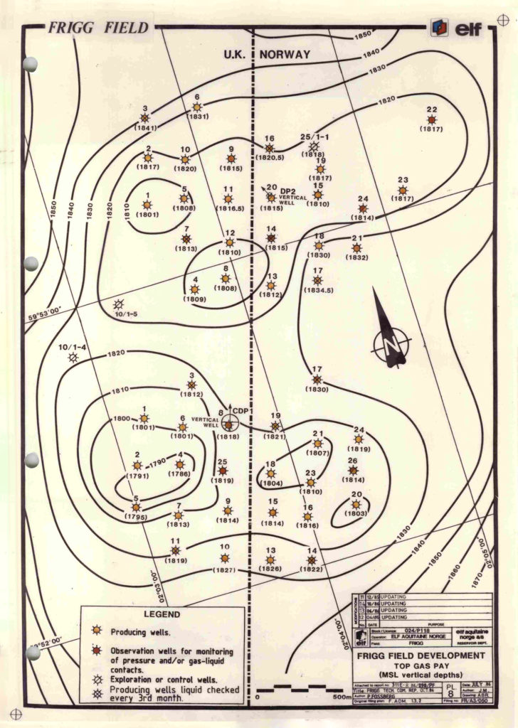
The wells

Frigg gas was produced through wells drilled from the concrete drilling platform 1 (CDP1) and drilling platform 2 (DP2). Beneath each of these installations, 24 wells were drilled to a depth of about 1 880 metres measured from the drill floor. Three casings were installed in each well, plus production tubing attached to the wellhead and Christmas tree (valve assembly) on the platform. The well control system comprised three valves on each well – an automatic safety valve 60 metres beneath the seabed, an automatic master valve on the wellhead and a manually-operated master valve on the Christmas tree.
Separation
 Brønnene, drift,
Production from each well flowed from the Christmas tree to a wellhead separator with two chambers. Sand and droplets of liquid were separated out in the first section and collected in a tank beneath the separator, while the gas continued via a choke into a manifold. There were two of the latter, each collecting gas from 12 wells before passing it on through 26-inch flowline to the TP1 or TCP2 treatment platforms.
The liquid accumulating under the separator was piped to a collection tank. Consisting of condensate (light oil) and water, it was transferred in a four-inch flowline to the process platforms. So little sand came up from the wells that the wellhead separators could be shut down as early as 1981.
Process control on the drilling platforms
Temperature, pressure and flow rates were measured at the outlet of each separator and displayed in the control rooms on the relevant drilling platform and on QP.
A need to vary the gas flow could arise from time to time. This was primarily accomplished by adjusting the choke valve at the well separator outlet. This adjustment could be made from the QP control room, the drilling platform’s control room, or a panel mounted alongside the choke.
Methanol injection
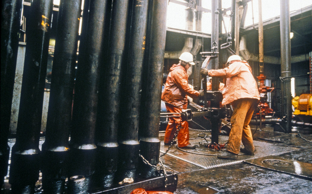 Boringer og brønner på Frigg, forsidebilde, Brønnene
Hydrate is a mix of hydrocarbons and water which resembles snow or ice. It can form when the temperature of the gas falls below a certain level, but is also pressure-dependent. To inhibit hydrate formation in the flowlines linking the drilling and processing installations, methanol was injected into the gas to act as an anti-freeze.
The pressures involved on the platforms meant that hydrate would not form as long as the temperature remained above 21°C. Gas emerged from the wells at a pressure of roughly 170 bar and a temperature of 40-45°C. When it passed through the choke valve, its pressure was reduced to 100-140 bar. Reducing the pressure of a gas also cuts its temperature at the rate of 0.3°C per bar. This meant that the temperature would fall below 21°C if the pressure declined below 100 bar, so methanol had to be injected to inhibit hydrate formation.
Pipeline cleaning
Once a pipeline had been in use for a time, condensate (light oil) and water could accumulate in it. The pipelines were accordingly cleaned at regular intervals with the aid of a “pig”. This device scraped the pipeline clean internally. Each drilling platform had three pig launchers and one retriever.