
Concrete Drilling Platform 1 – CDP1

 Bore- og brønnplattformen CDP1
It was originally designed and built as the manifold platform (MP1) for the pipelines to St Fergus. However, the drilling platform (DP1) jacket was lost during its launch. Another solution had to be found if gas deliveries were to start on schedule. It was accordingly resolved to convert the partly-built MP1 into the CDP1.
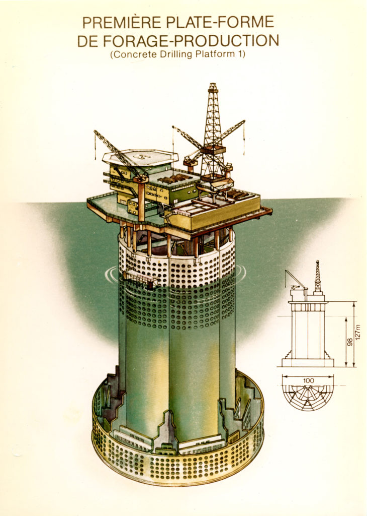
Designed by Europe Etudes in Paris as a consultant to C G Doris-Howard, this platform’s gravity base structure (GBS), plus the breakwater and support deck, were in prestressed concrete. But they were not built to Norway’s Condeep design. French designers were early adopters of concrete structures offshore. The first Doris installation was the Ekofisk tank in 1973, to be followed by CDP1 on Frigg.
Construction took place in Åndalsnes under the leadership of concrete platform builder Norwegian Contractors. The GBS was topped by 15-metre shafts fabricated by Steri at Ennery in France which carried the concrete support deck. A steel topside produced by ACMC Carpiquet in France was installed above this. The structure contained 5 000 cubic metres of concrete and 9 000 tonnes of steel. Production and processing equipment was delivered by Lummus France and Comsip, while the eight drilling modules came from Saipem Drilling.
The GBS was towed from Åndalsnes to Frigg in September 1975 and installed by ballasting down the structure until it rested on the seabed in 98 metres of water. A large crane was then erected on top of the support deck in order to lift the modules on board. Once everything was in place, this crane was demobilised and transferred to land. The GBS had an inner concrete shaft measuring six metres in diameter, surrounded by six cells. The gas flowlines to the TP1 treatment platform ran through this shaft.
 Bore- og brønnplattformen CDP1
Risers from the 24 wells terminated in wellheads installed on the 12 wells in each concrete cell. The drilling derrick on top could also be skidded over each wellhead, which was fitted with three safety valves – one downhole, one remotely operated master valve and one manual master valve.
Eighteen modules were installed on the support deck. They contained such facilities as wellheads and production equipment, process systems and power supplies.
The living quarters, with 80 berths and a helideck, were placed at the northern end of the platform, as far as possible from the derrick. Modifications were made to CDP1 in 1984-85 with the addition of a new drilling module and a new living quarters. These were built by Consafe in Sweden.
See technical drawings and documentation of CDP1 in the article Technical Documentation CDP1.