
Drilling platforms – operators

 Operatør bore- og brønnhodeplattformene, drift,
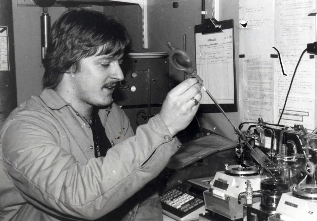
These operators had an overview of the whole process from the point where the gas came up from the sea until it was sent on to the processing platforms. They routinely toured the platforms to monitor pressure and temperature readings on various instruments, followed up the well maintenance programme, checked pressure and pressure-tested valves. If a valve was not fully sealed, it had to be greased. The operators monitored, manoeuvred and control the production process. They also supervised it with the aid of computerised systems in the control room. Other jobs included taking various samples. The composition of gas and condensate was sampled once a week, with the same samples taken on TP1 and TCP2 after processing. These were sent to the Dusavik offices for analysis. Other sampling included tests to identify the possible presence of bacteria in certain parts of the reservoir. Traces of iron in the formation water indicated bacteria which could have a corrosive effect on metal. Corrosion-inhibiting chemicals then had to be injected into the vulnerable equipment.
All results were carefully logged. Should abnormalities arise, the operator had to ensure that they were corrected. If they could not do so themselves, they called in an electrician, instrument technician or mechanic – depending on the job to be done. Another key task was to pump a cleaning pig at regular intervals through the flowlines to the processing platforms. This was done to remove possible condensate or sand deposits. A pig was introduced to the flowline through a launcher and carried by the gas stream to a retriever on TCP2 or TP1, where it was removed by the platform personnel.
Production continued around the clock, and work was accordingly organised in shifts. The night shift ran in the early years from 01.00 to 13.00, with the day shift occupying the other 12 hours. The period for night working was later changed to 19.00-07.00. Each platform had a senior operator and an operator, who also circulated between the drilling installations.
Wellhead, Xmas tree and choke
The wellhead forms the topmost part of the well, where the casing which lines the borehole terminates and is secured. The Christmas tree sits on top of the wellhead. This assembly of valves controls the flow pressure at the bottom of the well and the rate of production. Flow is regulated by a choke valve, which can be compared with a water tap (faucet). It is adjustable and used to optimise well flow. The choke makes it possible to manage production in a way which ensures optimum recovery from the reservoir.
The Christmas tree functions as a barrier to prevent an uncontrolled well blowout. A water tap, for instance, has a control valve. If that breaks or springs a leak, the main stopcock must be closed by hand. Similarly, it must be possible to close the Christmas tree valves on a gas production well if anything goes wrong.
Working conditions
 Kontrollrom på QP, drift, Operatør bore- og brønnhodeplattformene
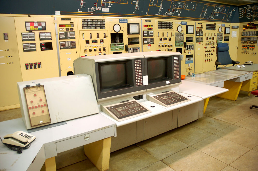
Each drilling platform had its own control room, where most of the process could be monitored. The choke valve, one of the most important components on these installations, could also be controlled from the QP control room. However, it had to be opened manually or from the drilling platform control room when starting up. The choke was used to adjust pressure in the flowline, since the gas could not enter the processing stage at its wellhead pressure. This valve could reduce or increase the gas flow. Other safety valves also controlled the pressure.
Other personnel on a drilling platform were its offshore installation manager (OIM), who also served as the process supervisor, a safety supervisor and a safety assistant in addition to the usual platform staffing – catering personnel, nurse, electricians, mechanics, instrumentation technician, crane driver, marine coordinator and a radio officer. The last of these also functioned as the rig officer, booked helicopters and assigned cabins. The drilling platforms were designed for remote operation, but only DP2 was run in this way from QP between 1996 and 2002.
Unstaffed periods
During the brief period when the platforms were actually remotely operated, a core team would visit and perform the necessary tests. This team was headed by an OIM. Pressure testing the valves was particularly important. The downhole safety valve, which sits a few hundred metres down in the production tubing, had to be retrieved occasionally for such tests. This work was coordinated by the reservoir department on land. The intervals between tests were eventually lengthened as the valves proved to be in good condition.
Optimising production
 Operatør bore- og brønnhodeplattformene, drift,
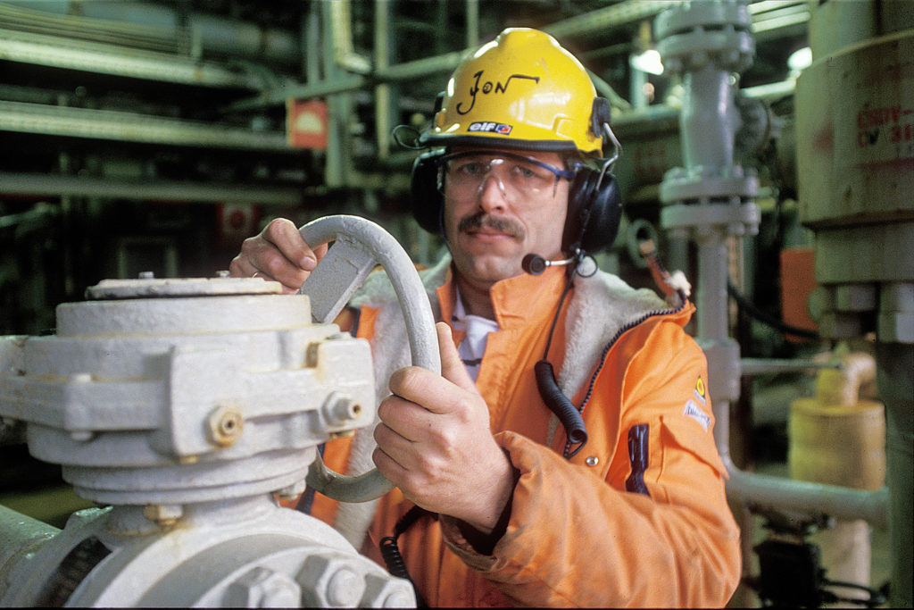
To ensure optimum production over time, the wells needed workovers or stimulation. The operators did much of the groundwork for such operations, which were carried out by people from various service companies. New wells were also drilled in the 1980s, first from CDP1 and then from DP2. The operators were not involved in the actual drilling operations, which were the responsibility of the drilling contractor. But they helped with preparations and followed up the contractor through the work permit system.
Ice plugs and methanol
The gas was hot when it arrived on CDP1 and DP2, but cooled during its passage through the submarine flowlines to the processing platforms. This posed the constant threat of blockages by hydrate forming in the flowlines. Hydrate is a mix of water and hydrocarbons which solidifies to resemble snow or ice crystals. It can form at a temperature of 23°C and a pressure of 150 bar. Methanol to serve as an anti-freeze was injected into the gas stream on Frigg before it entered a submarine flowline to a processing platform. The operators monitored the methanol intake and were also required to find solutions if hydrate nevertheless formed and caused a blockage. This could be done by raising the gas temperature or reducing its pressure, or by increasing the methanol dosage.
“We once got a hydrate plug because we began to lose the flow rate,” recalls former Frigg operator Finn Husberg. “We thawed the plug with methanol and reduced pressure at the other end of the line, which freed it. So much energy is involved, huge forces, that when the plug passed a curve in the flowline, which was 20 inches in diameter, the pipe shifted a good bit from its original position and broke some metal sheets in one of the [glycol] contactors on TCP2.”