
Treatment Compression Platform 2 – TCP2

 Prosessplattformen TCP2
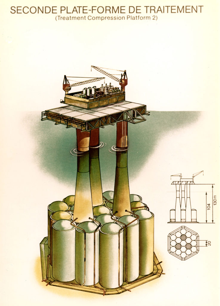
TCP2 and Statfjord A were the first platforms on the NCS supported by a Condeep gravity base structure (GBS). This comprised 19 concrete cells, each 20 metres in diameter and 42 metres high. The three shafts supporting the topsides reached a height of 126 metres above the seabed. The gas was piped on through the Frigg Norwegian pipeline (FNP) to Scotland.
The main contractor for the GBS was the Condeep group, which comprised Aker and the Norwegian Contractors joint venture between the Furuholmen, Høyer Ellefsen and Selmer construction companies. Work on this unit took place during 1976 in the Åndalsnes dry dock where the GBS for CDP1 had been built the year before. A leak in the dock delayed the work by almost a year. Once the base had been cast, it was towed out into the fjord for slipforming to continue. A total of 53 000 cubic metres of cement was required.
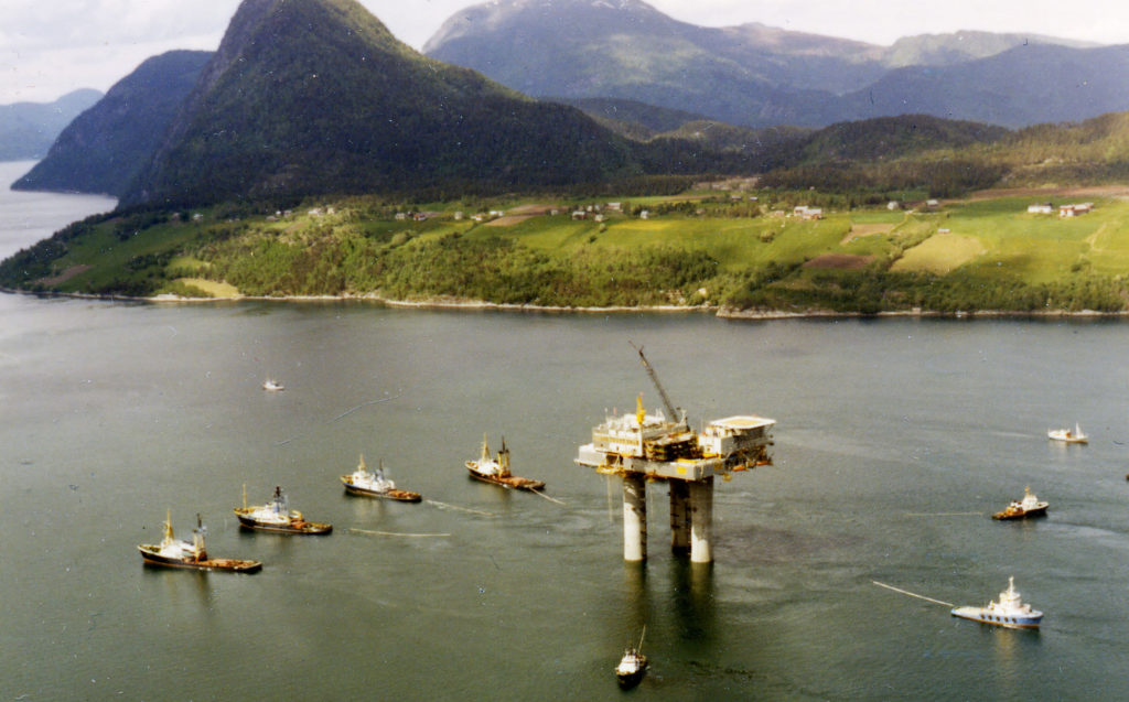
The towout from Åndalsnes began on 8 June. With the aid of five tugs, which reached a speed of two knots, the platform arrived on Frigg six days later. Bad weather prevented further work for several days, but TCP2 was positioned on the seabed on 22 June. It stood a few metres on the Norwegian side of the boundary, in 102 metres of water.
 Prosessplattformen TCP2, forsidebilde, engelsk,
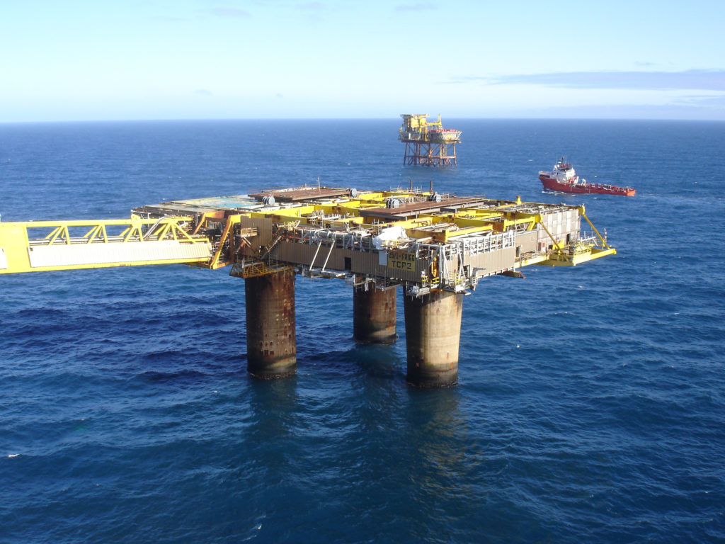
This was followed by hooking up the modules and pulling in flowlines from DP2. The bridge between TCP2 and TP1, built in Antwerp by Mercantile Marine Engineering and Graving Docks, provided the only surface border crossing between Britain and Norway.
Platform becomes operational
 Prosessplattformen TCP2,
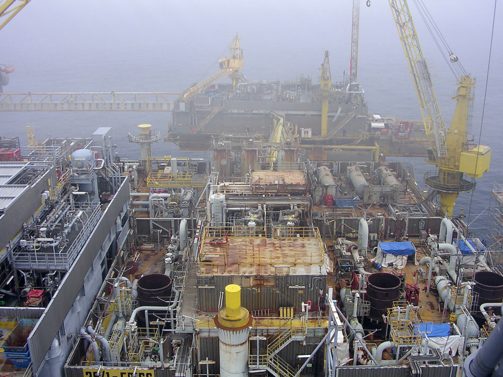
TCP2’s primary function was to process gas produced from the Norwegian side of Frigg. Condensate (light oil) and water were separated out and the gas dewatered. Pressure and volume were also checked before the gas was piped to Scotland. The platform normally processed gas from DP2, while the TP1 installation dealt with production from CDP1. However, flowlines between these platforms made it possible to switch around as required.
The gas processing system was split into three equal trains, each comprising a separator, a compressor, a dewatering unit (glycol contactor), a glycol regeneration system and a metering station. Each train had a capacity of 15 million cubic metres of gas per day. Two would normally be in operation, with the third in reserve.
TCP2 also had other duties. One was to supply the rest of the field with electricity. Two gas turbines from Sweden’s Stal Laval drove the generating sets. Traditionally, a turbine gets named for the saint on whose feast day it is incorporated in the field’s power system. This happened for the first turbine on 17 April 1981, so it was dubbed Elias. The second followed on 4 May and acquired the name Monica 1.
After the installation work had been completed, classification society Det Norske Veritas certified the platform as safe. Gas from DP2 then began to be processed in August 1978 and was piped to the receiving terminal at St Fergus in Scotland through the FNP via MCP-01.
Modifications
Gas pressure from the reservoir declined as production proceeded. But the British Gas Corporation wanted deliveries at constant pressure, and equipment had to be installed on Frigg to fulfil this requirement. This represented phase III in the development of the field. Three compressors, one for each process train, power generators and process control modules were installed. The compressors to serve both TP1 and TCP2 were installed between the separators and dewatering units on the platform. They were contained in a module built by Spie Batignoles Vigor in Orkanger. The generators came from OIS in Kristiansand and utilities were delivered by Nymo Mekaniske Verksted in Grimstad. During installation work, the platform was shut down for a long period. The first compressor became operational on 24 September 1981 and the last on 20 November that year.
The Frigg extension project was initiated in 1983, when a small compressor module was installed because of the additional flow of gas from North-East Frigg and Odin. Process equipment for East Frigg, comprising simple separators and metering systems, was connected in April 1988.
Two new modules were installed in 1993 to receive gas from Lille-Frigg. They were designed and fabricated by Kværner Rosenberg in Stavanger and Nymo. The gas was dewatered and exported to Scotland, with the condensate stripped of water and exported through the Frostpipe line via Oseberg to the Sture terminal near Bergen.
A major change occurred in May 1995 when the Frøy satellite was tied in. The biggest challenge with this development was to convert parts of the Frigg installations from pure gas production to also processing oil. This job took place without disrupting the flow of gas through TCP2. A new 3 400-tonne processing module had to be fabricated, and about 500 tonnes of additional equipment placed on the platform. Gas was initially split from the oil and water in a separator on the Frøy platform, then cooled down and injected with methanol to inhibit the formation of hydrate (hydrocarbon ice) before being piped to TCP2.
Oil and produced water were also pumped to this installation, while water for injection into the Frøy reservoir to maintain pressure was transported in the other direction through a 16-inch flowline. The Frøy gas was dewatered and exported to Scotland together with Frigg output, while the oil was dewatered and carried through Frostpipe to Sture along with condensate from Lille-Frigg. Because TCP2 was to receive oil from Frøy, a flare boom also had to be installed on the platform as a safety measure.
Shut in
Gas ceased to flow through the Frigg system in October 2004, and TCP2 was shut in for good.
See technical drawings and documentation of TCP2 in the article Technical Documentation TCP2.
 Prosessplattformen TCP2, engelsk,