
Treatment Platform No. 1 – TP1

 Prosessplattformen TP1, engelsk,
TP1 included the first concrete gravity base structure (GBS) to be built in the UK. A GBS sits on the seabed in a stable position because of its own weight. The Frigg unit was constructed in a dry dock at Ardyne Point on Loch Striven, west of Glasgow in Scotland. This site had been chosen because of the need for sufficiently deep water to float out the GBS. The dock was large enough to accommodate three structures simultaneously – Brent C and Cormorant A as well as TP1.
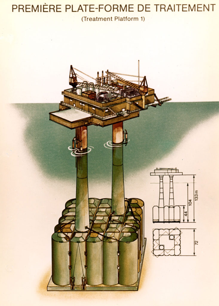
The GBS was developed by Sea Tank Company in Paris, and is one of four structures with this design in the North Sea. A consortium comprising Sir Robert McAlpine and Sons, which owned the dry dock, and Sea Tank Company secured the building contract in January 1974. Work began that April. The GBS comprises 25 concrete cells and two shafts supporting the topsides. A total of 70 000 cubic metres of concrete were used. After the base section had been cast in the dry dock, it was towed to a position 150 metres from land for the rest of the slipforming.
Ardyne Point had contracted to deliver TP1 by 15 May 1975, but a five-month strike meant that this date could not be met. Work on the steel module support frame and the topside modules fell behind schedule. The platform had to remain at land through the winter, and completion was delayed by roughly a year.
 Prosessplattformen TP1, engelsk,
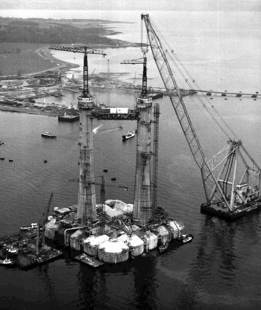
Loch Striven is only about 98 metres deep, while the GBS had to be submerged to a depth of 120 metres for mating with the module support frame. The concrete structure was accordingly towed out into Loch Fyne, where the water depth is 180 metres. This move took place in March 1976. Built at Construction Metalliques de Provence (CMP) and the Mardyck yard in the French port of Dunkerque, the 1 870-tonne module support frame was towed to Loch Fyne in the same month. It was lifted into place by the big ETPM 1601 and LB Meaders crane vessels in April 1976.
The tow-out of the 166 000-tonne platform from Loch Fyne began on 22 March 1976 and took a route west and north of Scotland and north of Shetland. Water depths at some points along the first section of this voyage are no more than 45 metres, so that ballast water had to be pumped out of the GBS to reduce its draught to 35 metres. Once past Inishtrahull, however, the water became deeper and the platform could be ballasted down to draw 65 metres.
TP1 was positioned in 104 metres of water on Frigg on 5 June 1976, just a metre out in relation to the planned location and oriented in the intended direction. It stood on the seabed by its own weight, supplemented by some seawater ballast.
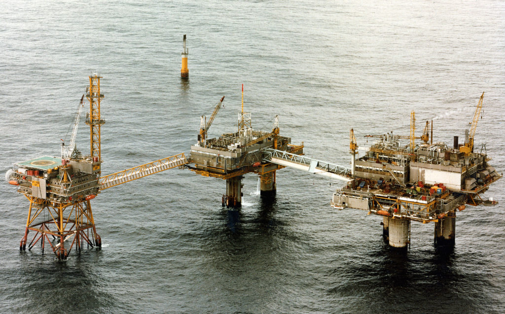
Once the platform was installed, the production modules were lifted aboard. These had been designed by McDermott Engineering in London and built by Mercantile Marine Engineering (MME) in Antwerp. TP1 was tied to QP and TCP2 by bridges.
 Prosessplattformen TP1, engelsk,
TP1 comes on stream
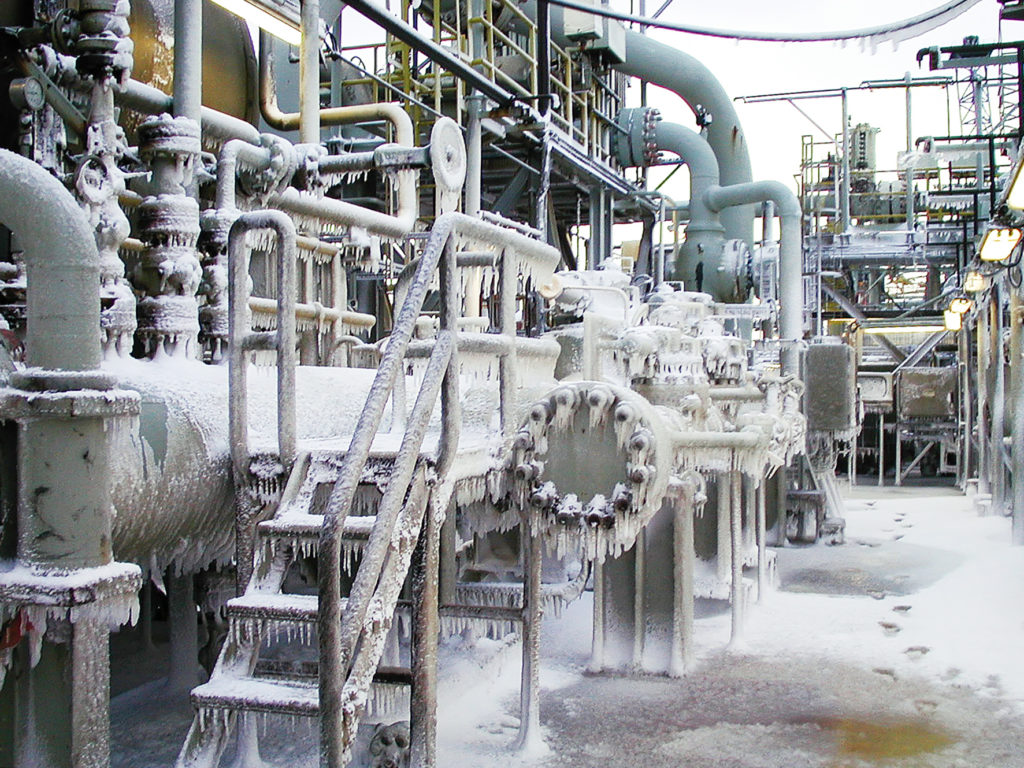
Treatment platform 1 (TP1) processed and dewatered gas transferred from drilling platform 1 (DP1) before it was transported through the Frigg UK Pipeline to Scotland. Three parallel trains for gas dewatering were installed, each comprising a gas/liquid separator, a gas dewatering unit (glycol contactor), a glycol regeneration unit and a metering station. Each train had a daily capacity of 15 million standard cubic metres. Two of the trains were operational at any given time, with the third in reserve. Liquids separated from the gas were treated in a separator to remove water from the condensate.
 Prosessplattformen TP1, engelsk,
The TP1 and TCP2 treatment platforms had a double function. Gas from CDP1 was normally transported via TP1 through the Frigg UK Pipeline to Scotland, while gas from DP2 went via TCP2 to the Frigg Norwegian Pipeline. But flowlines linking the two treatment platforms allowed gas from TP1 to be exported via TCP2 and vice versa. This provided full flexibility in the event of a possible production shutdown on one of the platforms.
Since TP1 was a pure gas facility, the concrete cells in its gravity base structure were not used for intermediate storage of oil. This installation came on stream in September 1977, when gas began to flow from CDP1.
Britain’s Alwyn field was tied into TP1 in November 1987 through a 24-inch gas pipeline in order to provide onward transport through the Frigg UK Pipeline. TP1 was converted in 1990 to a riser platform, and the gas processing plant was shut down. The FP flare platform tied to TP1 was removed after processing ceased on the latter installation.
See technical drawings and documentation of TP1 in the article Technical Documentation TP1.